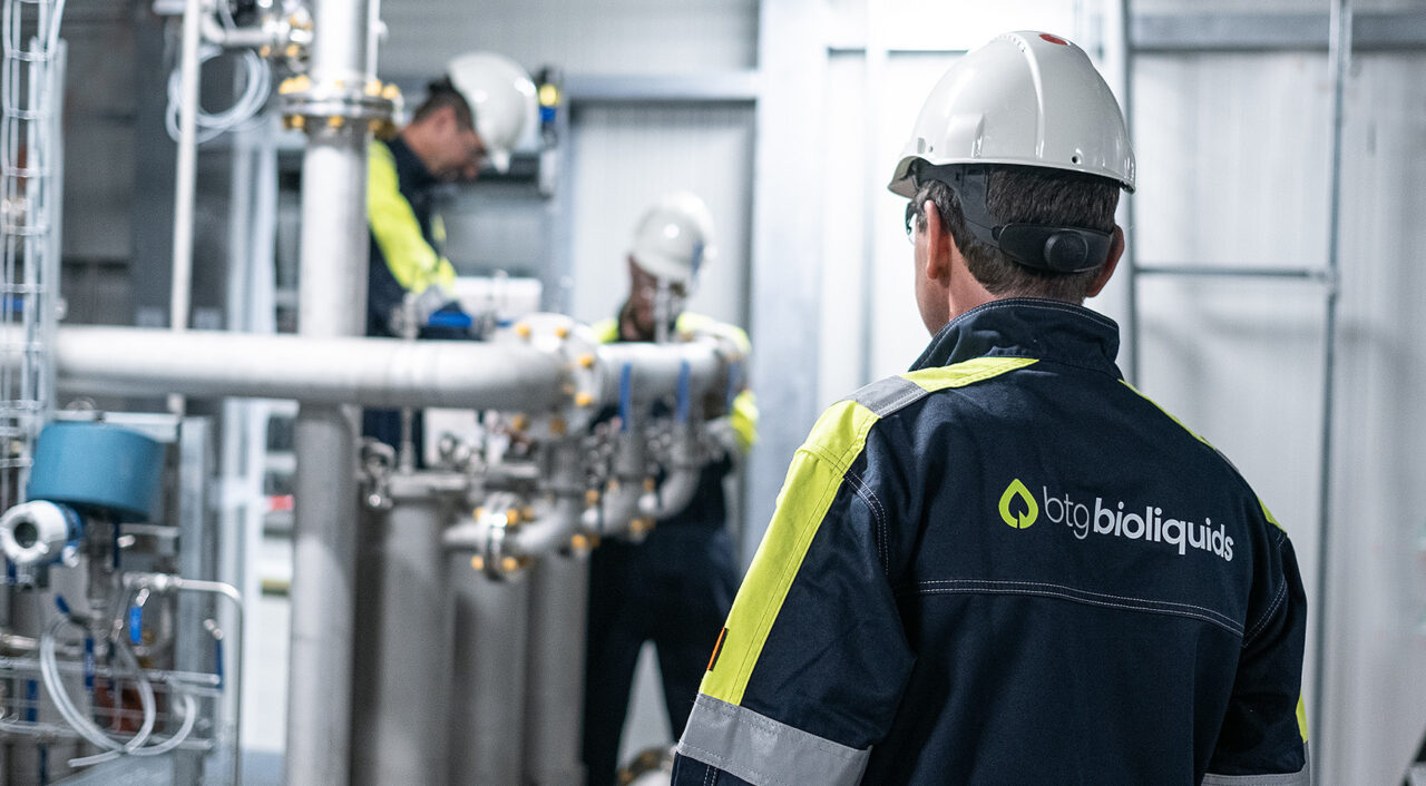
The most distinctive asset of our patented technology is the Rotating Cone Reactor (RCR). It allows for intense mixing without the use of an inert carrier gas. The RCR design results in a remarkably small reactor, reduced system complexity and a minimal down stream equipment size, compared to other pyrolysis technologies.

Our fast pyrolysis technology turns biomass residues into a renewable bioliquid that can replace fossil fuels. The key features of our technology – the exclusive use of biomass residues and the opportunity for local processing – make it a truly sustainable solution.

We contribute to a sustainable society, by producing bioliquids that replace fossil fuels.

Ardy Toussaint
Ardy Toussaint, Technical Manager
Step 1

Biomass drying and feeding

The (sized) biomass feedstock is taken from the biomass handling and storage section to the dryer where the moisture content is reduced to below 5%. The dried biomass is transported to a storage vessel and from there via the dosing system to the reactor.

Step 2

Mixing and condensing

The biomass is mixed and heated with hot sand in the reactor in the absence of oxygen producing pyrolysis vapours and char. Sand and char particles are removed from the pyrolysis vapours as they pass through the separator and cyclones. The vapours are condensed yielding the fast pyrolysis oil. Some non-condensable gases are extracted and used as fuel in the combustor.

Step 3

Closed sand loop and reheating

The separated sand and char are taken to the fluidised bed combustor. Here, the char is combusted together with the non-condensable gases to reheat the sand. The hot sand leaving the combustor passes the sand cooler which brings the temperature of the sand going the reactor to the optimal temperature for fast pyrolysis.

Step 4

Heat recovery and minerals

While the FPBO is taken to the storage tank, flue gases leaving the combustor are used to generate high pressure steam in the heat recovery boiler, together with the steam generated in the sand cooler. The high pressure steam may be used for E-power generation using a back-pressure steam turbine. The low pressure steam is used for boiler feed water generation, providing heat to the dryer and for external use. The mineral containing ash is removed from the flue gases by a filter and can be used as a soil fertilizer.

1
2
3
4

Our unique technology benefits

Due to the characteristics of our modified RCR (Rotating Cone Reactor) technology and the engineering and design of our fast pyrolysis process, we achieve lower CAPEX and OPEX than competing pyrolysis technologies. The plants we deliver are already economical at a feedstock availability of 5 tons per hour.

Find out more about the specifics or our technology, including:

  • No carrier gas needed, resulting in compact equipment design and low CAPEX
  • Skid mounted modules to ensure shortest possible onsite plant reassembly
  • Excess process steam and electricity production contributing to an improved OPEX
  • Commercially proven concept, with high feedstock flexibility
  • Stable bio-oil output

Tailored to local requirements

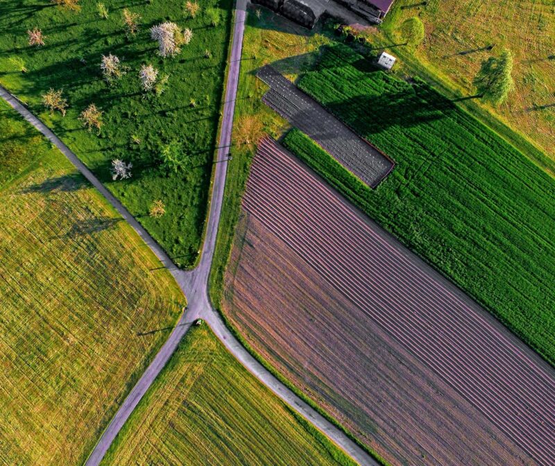
The input capacity of our pyrolysis plants is very well aligned with agricultural and forestry operations. Our plants can be located close to the source of biomass residues, to minimize biomass transportation. The local processing of residues offers significant and multiple benefits:

  • Due to the high energy density of FPBO, transportation is much more effective.
  • Most minerals in the biomass are recovered from the process and can be returned to the soil.
  • Local pyrolysis plants create additional income and employment in rural areas.
Gerhard Muggen
Gerhard Muggen | Managing Director

Request a preliminary feasibility assessment for a pyrolysis plant at your location.